
Free gyro principle
It has 3 degrees of freedom:
1. It is free to spin about spinning axis, i.e. spin.
2. It is free to rotate about vertical axis, i.e. drift.
3. It is free to rotate about horizontal axis, i.e. tilt.

Properties of a free gyro
1. Gyroscopic inertia(Rigidity in space)
This is the property that keeps the gyro spin axis direction fixed in space, even though the gimbals are moved. (When no force is exerted on spin axis direct)
2. Precession
Precession is the term used to describe the movement of the axle of a gyro under the influence of an external force. The direction of torque (force) on a free gyro rotor will be 90 degrees different to the direction of its effect, i.e. if we apply a torque about horizontal axis, the direction of movement will be around vertical axis. Here is said that gyre is precessed around vertical axis or vice versa.
Gyro axis movement at different locations on the earth
At poles
1. With gyro spin axis settled parallel to earth’s surface: Gyro drifts at the rate of 15°/h (360° in 24 hours) & No tilt.
2. With spin axis settled vertical to the earth’s surface: There will be no apparent movement of gyro spin axis (no drift & no tilt). Drift=15°/h sin (latitude)
On equator
1. With spin axis parallel to earth and at E-W direction: There will be maximum tilt (15°/h) & no drift.
2. With spin axis in N-S direction pointing the pole star: There will be no tilt and no drift.
Tilt=15°/h cos (latitude) sin (azimuth)
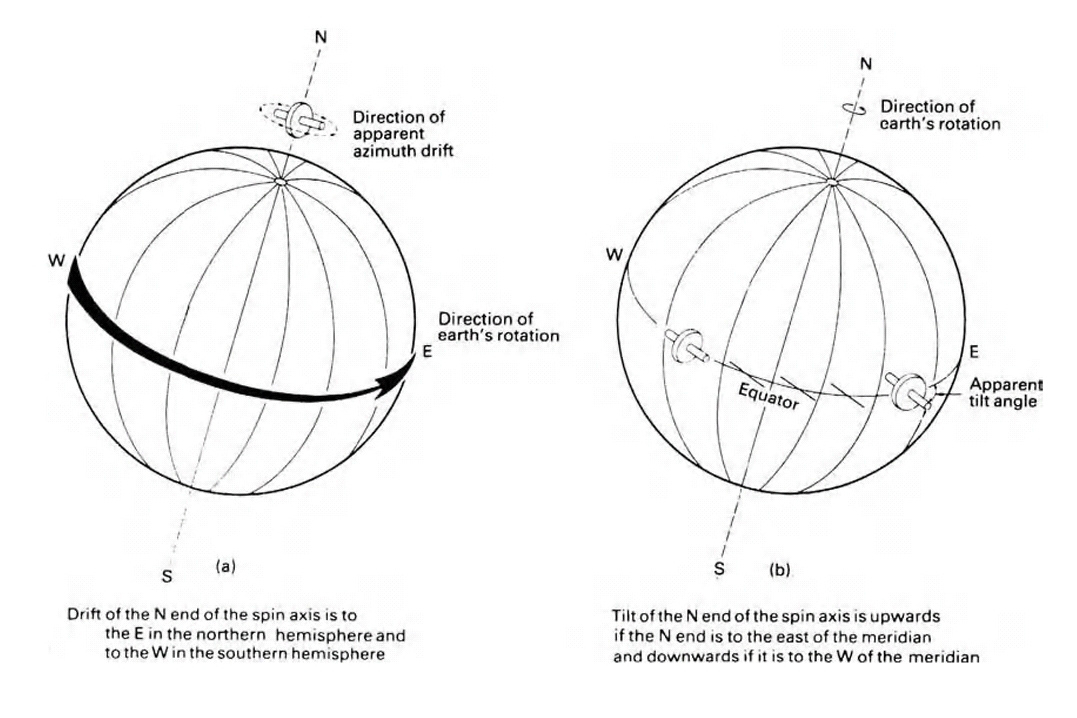
1: Drift in northern hemisphere is always eastward and in south hemisphere is westward. Note
2: If spin axis points east of the meridian the rate of tilt is upwards and if it points west of meridian rate of tilt is downwards.
Control Forces
1. Top Heavy Control Force


2. Bottom Heavy Control Force


Top heavy control using Liquid Ballistic Method
Simple methods of control are not practical in commercial compasses, because of the problems encountered with ship’s movement. An improvement is to use a LIQUID BALLASTIC to give a form of gravity as shown below. (Used in Sperry)

The principle is similar to that of top heavy gyro. The rotor spin direction is clockwise, as seen from north end, and hence when the gyro tilts up, it will produce a precession which moves the north end of spin axis to the west. The advantage of the system is that the liquid is chosen such that it is slow to respond to sudden changes caused by ship’s movement but will still respond to gradual changes produced by the earth’s movement.
Movement of the controlled or north seeking gyro
The figure shows the movement of the projection of the spin axis of a controlled gyro in the northern hemisphere. The gyro was initially set up parallel to the earth’s surface pointing slightly east of the meridian.
The following abbreviations are used in the figure:
Pc: Represents the gyro’s precession due to the control force. This depends on the gyro’s angle of tilt.
D: Represents the gyro’s rate of drift due to the earth’s rotation. The nearer gyro’s angle of tilt to the elevation of the pole star, the less rate of drift.
T: Represents the rate of change and direction of tilt. It depends on how far in azimuth the gyro is from the meridian.
Point 1: This is where the gyro was initially set up, slightly to the east of meridian, but parallel to the earth’s surface. The control precession Pc will be zero. D & T will be the same as for the free gyro.
Point 2: The gyro has now gained an angle of tilt, therefore a control force is developed which will produce precession Pc opposing the eastward drift. The rate of drift “D” will have decreased because the gyro is closer to the elevation of pole star. The rate of tilt upwards will have increased, because the gyro is pointing further east of the meridian.
Point 3: The angle of tilt has increased such that Pc now equals D, so there is no further eastward drift. The rate of tilt is therefore at its maximum upwards.
Point 4: The angle of tilt is now such that Pc is greater than D, which is still reducing as the gyro approaches the elevation of the pole star. The gyro moves westward towards the meridian. This reduces the rate of tilt increase upwards.
Point 5: The westward movement has brought the gyro to the meridian, which means there is no increase in tilt. The angle of tilt is now a maximum and therefore D is a minimum and Pc is a maximum. The gyro therefore continues its westward movement past the meridian.

Point 6: The gyro is west of the meridian, therefore the rate of change of tilt is increasing, but in a downwards direction, reducing the angle of tilt. The reduction in angle of tilt reduces Pc and increases D, thus reducing the rate of westward movement.
Point 7: The angle of tilt has decreased such that Pc equals D. This is the most westward the gyro will travel. Therefore the rate of decrease in tilt T is at its maximum.
Point 8: The angle of tilt has decreased such that Pc is less than D, and the gyro drifts eastwards. This movement towards the meridian reduces the rate of decrease in angle of tilt.
Point 9: The gyro is again parallel to the earth’s surface, so Pc is zero. The spin axis is pointing west of the meridian, so the movement of tilt is still downwards. The drift D is to the east and increasing as the spin axis moves away from the pole star.
Point 10: The gyro has again reached the meridian, so there is no further change in tilt. The angle of tilt is downward, so Pc now assists the eastward drift. This is a maximum since the gyro’s elevation is as far below the pole star as it will reach. The gyro therefore moves past the meridian back to point 1. The gyro will then repeat its path around the ellipse, continuously moving around the meridian. The controlled gyro is therefore said to be NORTH SEEKING.
No comments:
Post a Comment